Saturday, September 29, 2007
Dialog Window or Command Pop-up gone
Your pop-up may be off screen: start themmand, on the keyboard use the combination of ALT+SpaceBar+M then use the arrow keys on your keyboard to nudge it back to view (this is a Windows feaure, you can use it to recover any lost pop-up in LT or other programs).
You can also change the resolution of your monitor to lower settings, the layer manager will show, move it to be centered, then change resolution back. ◦
Saturday, September 22, 2007
Two commands to Explode Entities
Exploding a Block sometimes gives us undesirable results. Often a Block is created from entities on Layer 0, so that it can be inserted on any Layer and thus inherit the properties of the insertion Layer. When exploding a Block of this type, all the components revert back to Layer 0.
XPLODE command (notice the missing E) works similarly to EXPLODE except it gives you the opportunity to override component entity properties. You can control the target Layer, Line type, Line weight, and Color, or Inherit all properties from the Block insertion.
You can also control what you explode individually, or globally (covers all entities being exploded).
Explore both in HELP in LT for usage instructions. ◦
Two commands to Explode Entities
Import Spreadsheets and Export Tables from LT
To import a spreadsheet (MSExcel used here for an example) into AutoCAD LT:
- Open the MSExcel file.
- Highlight the desired cells you want to import into LT.
- Choose Edit-->Copy from the pull down menu (copy selected cells to clipboard)
- Minimize MSExcel, do not close the program or you will lose the selected cells copied to the clipboard.
- Open LT and a new or current drawing.
- Choose Edit > Paste Special from the pull down menu.
- In the Paste Special dialogue box, choose "AutoCAD LT Entities".
- Choose an insertion point for the table. Remeber that the table size, text height ..etc, is based on the current Table Style.
- Open LT and a drawing containing a completed table.
- Select the table and right-click.
- In the right-click menu choose the Export option.
- Save the table in a folder. Notice that the table is saved as a .CSV file (Comma Delimited).
- In MSExcel, go to File-->Open in the pull down menu.
- In the Open dialogue box, change the "Files of Type" option at the bottom to "All Files".
- Navigate to the folder containing the .CSV file and select the file to open.
Import Spreadsheets and Export Tables from LT
Free Online Tutorials Links
- Lynn Allen's free video Tips and Tricks online HERE.
- LT2008's new text/annotation features explored HERE.
- Creating attributes: labels, tags and editable text inside blocks HERE and in this MOVIE. And in case you need it, here is a Block OVERVIEW as well as WBLOCK command. Many more links found HERE.
- An overview of Palettes with Blocks HERE.
- Help with PLOT command provided at the great SITE. And more importantly, understanding UNITS and Scales settings inside AutoCAD HERE.
- CUI video tutorials HERE: originally developed for 2006, still very useful for an overview if you use later versions. Additional customization tips and ideas HERE.
- eTransmit command, the best way to send/email drawing files to others HERE.
- Using Groups in AutoCAD, tips and insight HERE.
- Creating a Dynamic Block in LT2007 and higher HERE: this example creates a door block HERE to see it all in action.
- Layers and Linetypes overviews HERE.
- Dealing with gaps, either in lines, plines or hatch areas, click HERE.
- Setting up text and dimensions, PART1 and PART2. More links on Dimensioning HERE and HERE for Text.
- Selection options other than W and C discussed HERE.
- Creating your own custom Plot Style Table (CTB) HERE.
- Creating your own custom simple linetype HERE.
- Creating and using Layer Filters HERE.
- Learn how to best use Grips with objects in AutoCAD HERE.
- Tables in AutoCAD are introduced HERE as well as this SITE.
- Paperspace/Layouts overview explained in TWO VIDEOS. Many more links HERE. Examine some good links on VIEWPORTS as well.
- OPTIONS command and it's many tabs and selections explained HERE.
- Understanding Xrefs and paths HERE.
- Using OTRACK, or Object Snap Tracking new to LT2007 and higher HERE.
- POLAR, or Polarmode use, and alternative to ORTHO on/off discussed HERE.
- Rotating views in your drawing discussed HERE.
For LT2008 tutorials on CD, 100 video lessons in 10-hours for one low cost, review the option to purchase HERE.
Free lessons here that comes from a great book LT2008 For Designers, click HERE.
More LT lessons here: LT2005, LT2007 and LT2008.
◦Free Online Tutorials Links
Wednesday, September 12, 2007
File Name missing at PDF prompt
FULLPLOTPATH is a variable added in 2006 to help overcome AutoCAD/LT's ability to overwhelm drivers that can't handle receiving the full path of the file in the plot. SImply type it at the command line in LT, and when prompted set it to 0 (zero). Your PDF driver should start placing your DWG file name in the box when prompting you for the PDF file's name.
And your troublesome Plotter or Printer driver may start behaving as well if you've had issues with them and LT. ◦
File Name missing at PDF prompt
LAYER command right-click options
More LAYER command features and abilities to follow in future blog entries. Stay tuned.
◦LAYER command right-click options
Monday, September 10, 2007
Fail to Create CommCntrClientSink object!
In most circumstances, using that Registry Cleaner's Undo or Restore feature fixes the problem, most quality products also include an exclusion option where you can add AutoCAD/LT to the list of programs not to touch.
If you use a freebie or a bargain cleaner, they don't restore or recover well. A repair reinstall of LT fixes the problem as noted HERE.
If not, you need to go a step further and completely uninstall all Autodesk products on your system as discussed HERE, then reinstalling them after a Windows restart.
Click on this for a GOOGLE search on the topic and other solutions posted.
Don't forget to backup all your LT customizations first, often, and regularly. ◦
Fail to Create CommCntrClientSink object!
Sunday, September 9, 2007
Recovering Backup files
- BAK files are backup files created on manual Saves, they reside in the same folder as your DWG file and all you have to do to recover one is to rename the file extension (if you have that feature turned on in Windows Explorer) from BAK to DWG.
Of course, you need to turn on BAK file creation first to get them: See screenshot below in OPTIONS command. Some I.T. personnel may not realize how important these files are so you need to push to have them if necessary for instant recovery as opposed to I.T.'s day-old recovery. - SV$ files are automatic timed backups of drawings created by turning on AUTOSAVE in LT. This should never be considered a replacement for a manual save, this feature exists solely as a backup to the above in case of an LT or system crash only: this autosave file is always deleted on successful AutoCAD/LT exit. These files are stored in the temp files folder under
You need to turn on the Autosave feature first to get them: See screenshot below in OPTIONS command. Rename the file extension (if you have that feature turned on in Windows Explorer) from SV$ to DWG. - AC$ files are temporary AutoCAD working files for various functions (undo, hidden lines...), ac$ files do not contain drawing data, you can't use them for anything or recover any data from them for your use.
Recovering Backup files
Saturday, September 8, 2007
Design Center's other features
- You can import content from another DWG file into your current one, such as Linetypes, Layers, Text Styles, Dim Styles, Table Styles, Blocks, Xrefs and Layouts.
- Using the Open Drawings tab, you can access the above content from ALL the current files you have open at the time, so you don't have to go browsing for the files first. You can also use the History tab the same way, except to access files you recently opened in LT.
- You can use ADCNAVIGATE command to go directly to a folder before you open ADCENTER: great customizing tip if you have many folders that you access regularly for content.
- You can drag and drop a DWG file into your current file to INSERT it as a block. If you drag that DWG file with the mouse's right-key, you get the option to start the full INSERT command pop-up, or attach that file as an XREF.
- You can set a folder to be the default go-to folder everytime you start Design Center: in the Folders tab, navigate to that folder, then right-click and select Set As Home.
- You can create a ToolPalette of all the dwg files from ADCENTER without doing it manually yourself: in the Folders tab, navigate to that folder, then right-click and select Create Toolpalette Of Blocks.
- You can drag and drop single Hatch Patterns from .pat files into your file, without using BHATCH command or placing them in any search path.
Design Center's other features
Right-click button settings
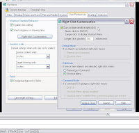
LT2004 and higher offer a compromise that is more productive than either option alone: A new time sensitive right-click. When this ability is turned on, a quick click of the right mouse button is the same as pressing
To set, start OPTIONS command, choose the User Preferences tab, turn on Shortcut Menus in Drawing Area selection, choose the Right-click Customization button: turn on Time Sensitive Right Click.
Change the time interval as needed until you find the setting most comfortable with your hand and mouse.
◦
Right-click button settings
Text plots in outline only
- Set the FILL command to on.
- Set the FILLMODE system variable to 1.
- Set the TEXTFILL system variable to 1.
- In the Plot dialog box, clear Hide Objects. If you need this setting for the rest of your drawing, you will need to change to SHX fonts in your text styles.
- Turn off the Hideplot property of the viewport. If you need this setting to achieve a desired plot ability, you will need to either change to SHX fonts in your text style or place the text in Paperspace out of the viewport.
- Turn off Shadeplot > Hidden Property of Viewport in LT2004, LT2005, and LT2006.
Text plots in outline only
No Linetypes in Layouts
The user must change the setting for the layout variable PSLTCALE (or better yet, copy a preset Layout from a template that is set correctly instead of randomly starting a layout from scratch). PSLTSCALE controls linetype scaling of objects displayed in paperspace viewports.
The variable has two setting options:
0 (or off) Linetype dash lengths are based on the viewport scale, they are NOT the same spacing.
1 (or on) If TILEMODE is set to 0, dash lengths are based on paper space drawing units, even for objects in model space. For any linetype, the dash lengths of a line in a viewport are the same as the dash lengths of a line in paper space.
The Global Scale Factor value controls the LTSCALE system variable, which changes the linetype scale globally for both new and existing objects.
The Current Object Scale value controls the CELTSCALE system variable, which sets the linetype scale for new objects. The CELTSCALE value is multiplied by the LTSCALE value to get the displayed linetype scale. You can easily change linetype scales in your drawing either individually or globally. ◦
No Linetypes in Layouts
Entering Surveyor Bearing and Distance
For example:
Command: LINE
Start Point: Select a start point
Next Point: @ 123.45 < N 45 D 10' 15" E
Next Point: @ 678.90 < S 25 D 20' 25" W
NOTE: no spaces needed between point entry text, shown here just for clarity.
Syntax description: @ sign is for relative to the start or last point. Next comes the Distance. Last is the Bearing. Its enclosed in the quadrant NE, NW, SE, SW. Letter D is to indicate the degrees. ◦
Entering Surveyor Bearing and Distance
Just type it at the command line
Not all commands or variables exist in LT as a menu pick or a toolbar button, so feel free to just TYPE the command at the command prompt in LT (if you turned it off or hid it, reposition it and turn it back on): without the command line available you are also missing out on many prompts and additional feedback LT is providing you. ◦
Just type it at the command line
Turn on the MAX in LT
Explore MAXACTVP variable in HELP, it controls how many active viewports you can see at anyone time. Limit is 64 though.
You need to create a large ARRAY and notice that LT hits a limits and stops. You can change this limit by setting the MaxArray system registry variable using SETENV and entering a number between 100 and 10000000. MaxArray must be entered with the capitalization shown.
You create, or try to, a very dense hatch pattern and LT objects that the hatch is too small or the dash length is too short: first make sure that SOLID hatch is not what you really need. If that's not the case, the hatch object limit is set by the MaxHatch environment setting: change this limit by setting the MaxHatch system registry variable using SETENV and entering a number between 100 and 10000000. MaxHatch must be entered with the capitalization shown.
LAYER command is not sorting all your file's layers or blocks alphabetically or any other order you select: explore MAXSORT variable in HELP in LT, inclrease the number displayed until the sorting problem is resolved. ◦
Turn on the MAX in LT
GEDIT or GEDIT 3 Error messages
LT2004 required the Service Patch to be installed to remove the symptom/cause noted above. If you have done this or are using a version of LT higher than 2004 and you still get this problem, so far it's been solely attributed to a conflict on your PC with another software package, and often requires that software package to be removed or updated.
Current solutions can be found at these following links:
Gedit3 Topic Page
Autodesk Support
Autodesk Discussion
Google Search ◦
GEDIT or GEDIT 3 Error messages
Friday, September 7, 2007
Control the prompt order for attributes in blocks
When creating a block, the selection order of the attributes is key to controlling the prompt order of the attributes when you INSERT the block.
While in BLOCK command, select the attribute definitions individually in the order you want to be prompted, then select the rest of the geometry/entities that will be the block. Start INSERT command and test your block, make sure ATTREQ variable is turned on.
◦Control the prompt order for attributes in blocks
JPG, PNG, BMP, TIFF and more from LT
To use this ability, you first need to set up a Raster File plotter, then PLOT to that format. Setup is as follows:
- Choose File > Plotter Manager.
- Choose 'Add-A-Plotter Wizard'.
- Choose Next, then Next again (accepting My Computer).
- Under Manufacturers, choose 'Raster File Formats'.
- Under Models, choose the raster file format you need.
- Choose Next until the Finish button becomes available. Note that some additional options exist to set if you so desire, including the ability to control the raster file background color.
Now start PLOT command, select the plotter you just create, and use any or all of PLOT command's options and features to create your custom raster file.
Click HERE for Autodesk's topic "Understanding dpi resolution with the Raster File Formats HDI plotter driver".
◦JPG, PNG, BMP, TIFF and more from LT
Simple and quick entities Alignment
You can use the PROPERTIES palette to adjust text justification before changing its alignment. ◦
Simple and quick entities Alignment
WBLOCK command hidden feature
The command line version, -WLBOCK (note the dash), has some interesting additional abilities:
- Entering the name of an existing block writes that block to an external file. Note that this function is not available with an external reference (xref) or one of its dependent blocks.
- Entering an equal sign (=) specifies that the existing block and the output file have the same name. Note that if no block of that name exists in your open drawing file, the prompt is displayed again and you must select another block name.
- Entering an asterisk (*) writes the entire drawing to the new output file, except for unreferenced symbols. Model space objects are written to model space, and paper space objects are written to paper space. A great way to creat a new file but still maintain existing layouts.
Note: After the file is created, the selected objects are deleted from the drawing. You can use OOPS to restore the objects.
◦WBLOCK command hidden feature
Cycling through overlapping objects in LT2007 or higher
Holding CTRL and press SPACEBAR is now reserved to cycle through overlapping subobjects (faces, edges, and vertices) on 3D Solids. ◦
Cycling through overlapping objects in LT2007 or higher
Cannot move LT's toolbars and palettes
A lock icon in the status bar tray indicates whether toolbars and windows are locked. Right-click the icon to display locking options.
To temporarily override the locked status, hold the Ctrl key while moving the toolbar or window. The lock status is also controlled by the LOCKUI system variable, with the following options:
0 Toolbars and windows not locked1 Docked toolbars locked
2 Docked or anchored windows locked
4 Floating toolbars locked
8 Floating windows locked ◦
Cannot move LT's toolbars and palettes
Redefine block entities to ByLayer
To repair such a setting in LT2008 or higher, redefine the block(s) with the SETBYLAYER command.
In older AutoCAD versions you can use the BEDIT or BLOCK commands to redefine the block(s), choice is limited by your LT version. ◦
Redefine block entities to ByLayer
Opening Autocad/LT starts MSOffice installer
If un-installing, restarting Windows and re-installing one or both of those applications does not fix the problem, Microsoft suggests the following as a fix:
http://support.microsoft.com/kb/290301/en-us ◦
Opening Autocad/LT starts MSOffice installer
MULTIPLE command's intersting ability
It has a very simple function: it repeats whatever command you type right after it. For example, you need to use MOVE or FILLET or CHAMFER commands etc. on many objects individually. At the command line, type MULTIPLE then the command you want to repeat, then use as normal. Every thime you finish the command, it restarts. To cancel, simply tap the ESC key on your keyboard.
To things to note about this command: it does not repeat any parameters within the command, it just repeast the command as if you just started it. It also does not work on commands that present you with a dialog box. ◦
MULTIPLE command's intersting ability
Comparing full AutoCAD to LT
Missing Drawing commands:
Mline, MlEdit, MlStyle, 3dface, 3dmesh, Tabsurf, Edgesurf, RevSurf, Rulesurf, Sphere, Pface, Sketch
Missing Raster/Image commands:
ImageAttach, ImageClip, ImageQuality, ImageAdjust, Transparency
Missing Common commands:
XClip, VPClip, QDim, DXBin, Load, PsIn, PsOut, PsFill, Shell, Align, Cal, Attredef, Battman, Battorder, Attsync, Eattedit, Eattext, Refedit, Attsync, Mline, Bedit (added in LT2007)
Missing Variables:
Offsetgaptype, FieldEval, ACADLSPASDOC, USERS1-5, OSNAPZ
Missing Extras:
Truecolor abilities (256 limit), MVSETUP, LISP, VLisp, NetLoad command, VBA, DBconnect, ARX/ObjectARX, ActiveX, most functions from Express Tools (Layers added in LT2007), Object Snap Tracking (OTRACK added in LT2007), Table Fields, Sheet Set Manager (SSM), expanded PUBLISH (DWF only option in LT)
Missing Pan/Zoom/3D commands:
3dOrbit, 3dcOrbit, 3dZoom, 3dZoomTransparent, 3dPan, 3dPanTransparent, 3dclip, 3dSwivel, 3dRender, 3dDistance, Camera
Missing 3D-Surfaces:
Box, Wedge, Pyramid, Cone, Sphere, Dome, Dish, Torus
Missing 3D Operations:
3dArray, Rotate3d, Mirror3d
Missing ACIS commands:
Cylinder, Torus, Box, Cone, Extrusion, Interfere, Union, SolidEdit, Rotation, Section, Slice, AcisIn, AcisOut, StlOut, AmeConvert
Missing Rendering commands:
Render, Scene, Light, Mat, Matlib, Mapping, ShowMat, Background, Fog, LsNew, LsEdit, LsLib, Replay, ImageSave, 3dsout, 3dsin, Rpref, Stats
Only AutoCAD MEP for an Object Enabler available (no Architecture/adt OE: supposedly fully built in but then why is there one for full autocad, no Mechanical/Civil/MAP OE, No Raster Design option, No Vault etc.).
No AutoCAD User Profiles.
Nothing above is crippling to most LT users, and does not in any way dimish LT as a tool. If you just use LT for adjacent seat users, consider Autodesk's DwgTrueView and DesignReview, both free, for all users that really don't need any kind of cad-file editing ability on their PCs. ◦
Comparing full AutoCAD to LT
Wednesday, September 5, 2007
Create an EPS file in LT
The following is a tip to creating EPS files for import into graphics programs like Adobe's Photoshop and Illustrator programs:
- At the command line, type PLOTTERMANAGER
- Double click on Add-A-Plotter Wizard
- Choose My Computer
- Select Manufacturers: Adobe
- Select Models: Postscript Level 1 Plus
- Check the option to Plot to File
- Name this new driver EPS
Create an EPS file in LT
Viewport Zooms after entering
First, lock your viewport (a great habit on it's own), then double-click inside it. At the command line type UCSFOLLOW, and set it to 0 (zero). You may now safely unlock your viewport, if you must. Don't forget to repeat in every other viewport in this file.
Explore UCSFOLLOW in Help in LT and explore it's feature. ◦
Viewport Zooms after entering
Tuesday, September 4, 2007
Searching for LT content
Start Design Center (ADCENTER command or CTRL+2), click on the Search button, and use the new pop-up to select what you are looking for plus other search parameters to find your content quickly.
ADCENTER command can also be used to identify where a drawing file is being Xrefed.
◦
Searching for LT content
Free AutoCAD demo videos
AutoCAD 2008 include topics such as Introduction, DWF Underlays, DGN Support, Layer Properties, Set Object Properties ByLayer, Layer Notification, Layer Lock and Fade, Layouts and Sheets, Traditional Annotation Scaling, New Annotation Scaling, Dimensions, Multileaders, Text, and Tables.
AutoCAD 2007 and AutoCAD 2006 also available. ◦
Free AutoCAD demo videos
AutoCAD slow at startup, and other slow issues
Monday, September 3, 2007
Recover Defective Drawing Files
- Repair a Damaged Drawing File
If a drawing file is damaged, you can recover some or all of the data by using commands to find and correct errors. When an error occurs, diagnostic information is recorded in the aclt.err file, which you can use to report a problem.
A drawing file is marked as damaged if corrupted data is detected, or if you request that the drawing be saved after a program failure. If the damage is minor, sometimes you can repair the drawing simply by opening it. Otherwise, you can use the following:
RECOVER command. Performs an audit on, and attempts to open, any drawing file.
RECOVERALL command (LT2008 and higher). Similar to recover, it additionally operates on all nested xrefs. The results are displayed in the Drawing Recovery Log window.
AUDIT command. Finds and corrects errors in the currently open drawing file. - Create and Restore Backup Files
Backup files help ensure the safety of your drawing data. If a problem occurs, you can restore a drawing backup file. Computer hardware problems, power failures or surges, user mistakes, or software problems can cause errors in a drawing. By saving your work frequently, you can ensure a minimum of lost data if your system fails for any reason. If a problem occurs, you can restore a drawing backup file.
In the Options dialog box, on the Open and Save tab, you can specify that backup files are created when you save drawings. If you do, each time you save a drawing, the previous version of your drawing is saved to a file with the same name and a .bak file extension. The backup file is located in the same folder as the drawing file.
You can revert to your backup version by renaming the .bak file in Windows Explorer to a file with a .dwg extension. You may want to copy it to a different folder to avoid overwriting your original file. - Recover from a System Failure
A hardware problem, power failure, or software problem can cause this program to terminate unexpectedly. If this happens, you can restore the drawing files that were open. If the program fails, you can save your current work to a different file. This file uses the format, DrawingFileName_recover.dwg, where DrawingFileName is the file name of your current drawing.
After a program or system failure, the Drawing Recovery Manager opens the next time you start AutoCAD LT. Drawing Recovery Manager displays a list of all drawing files (DWG and DWT) that were open.
Note: Unsaved drawings that are open at the time of an unexpected failure are not tracked by the Drawing Recovery Manager. Be sure to save your work after you begin, and regularly thereafter.
For each drawing, you can open and choose from the following files if they exist:
DrawingFileName_recover.dwg
DrawingFileName_a_b_nnnn.sv$
DrawingFileName.dwg
DrawingFileName.bak
Note: The drawing, backup, and recover files are listed in the order of their time stamps—the time when they were last saved.
Doubleclick a top-level drawing node listed under Backup Files to display up to four files as listed above. Right-click any node under Backup Files to display shortcut menu options.
If you close the Drawing Recovery window before resolving all affected drawings, you can open Drawing Recovery at a later time with the DRAWINGRECOVERY command.
Recover Defective Drawing Files
Change the Default Drawing Folder
Restarting LT helps set it if it acts up after the change. ◦
Change the Default Drawing Folder
TrustedDWG messages and concept
TrustedDWG™ Drawing Files
DWG, DWT, and DWS files that are created with Autodesk applications and RealDWG™-based applications are trusted by Autodesk. When you open a TrustedDWG file, the following icon displays in the application status bar or the drawing status bar.
If the DWGCHECK system variable is set to On (1), an alert box is displayed if:
- The drawing file format is AutoCAD Release 14 or later and
- The drawing file was not saved by an Autodesk application or RealDWG-based application.
TrustedDWG messages and concept
F1 key reprogram to stop calling HELP
1. Right-click on a toolbar and select Customize... to open the CUI Editor.
2. In the upper left area, expand Keyboard Shortcuts and then Shortcut Keys.
3. Drag a command from the command list below into the Shortcut Keys (I used the first command .XY).
4. The command should now be in the Shortcut Keys area. This creates a new shortcut key with the same name as the command. Right-click on the new shortcut key and select Rename. Rename it to "F1 Remap" (no quotes).
5. In the properties area for the new shortcut key, Change the description to something else (or just delete the text there).
6. Change the macro to the following, which basically cancels any running command, you can add another command if you desire: ^C^C
7. In the Keys text area of the access heading, clickinside the text area to activate it and then press the button on the right with the three dots.
8. The shortcut keys dialogue box comes up. Place a cursor in the area called "Press new shortcut key:" and press the F1 Key on your keyboard. F1 should now appear in that box. Click on the Assign button. F1 should now appear in the Current Keys section. Click on OK.
9. Click on Apply in the CUI editor and then OK.
If you have LT2005 or lower, click HERE. ◦
F1 key reprogram to stop calling HELP
Sunday, September 2, 2007
Keyboard shortcuts in LT
CTRL+0 Toggles Clean Screen
CTRL+1 Toggles Properties palette
CTRL+2 Toggles DesignCenter
CTRL+3 Toggles the Tool Palettes Window
CTRL+7 Toggles Markup Set Manager
CTRL+8 Toggles the QuickCalc calculator palette
CTRL+9 Toggles the command window
CTRL+A Selects objects in drawing
CTRL+SHIFT+A Toggles Groups
CTRL+B Toggles Snap
CTRL+C Copies objects to Clipboard
CTRL+SHIFT+C Copies objects to Clipboard with Base Point
CTRL+E Cycles through isometric planes
CTRL+F Toggles running object snaps
CTRL+G Toggles Grid
CTRL+H Toggles PICKSTYLE
CTRL+I Toggles COORDS
CTRL+J Repeats last command
CTRL+L Toggles Ortho mode
CTRL+M Repeats last command
CTRL+N Creates a new drawing
CTRL+O Opens existing drawing
CTRL+P Prints current drawing
CTRL+R Cycles layout viewports
CTRL+S Saves current drawing
CTRL+SHIFT+S Brings up the Save As dialog box
CTRL+T Toggles Tablet mode
CTRL+V Pastes data from Clipboard
CTRL+SHIFT+V Pastes data from Clipboard as a Block
CTRL+X Cuts objects to Clipboard
CTRL+Y Cancels the preceding Undo action
CTRL+Z Reverses last action
CTRL+[ Cancels current command
CTRL+\ Cancels current command
CTRL+TAB Cycles through all open DWG files in your current LT session
CTRL+PAGE UP Moves to the next layout tab to the left of the current tab
CTRL+PAGE DOWN Moves to the next layout tab to the right of the current tab
F1 Displays Help
F2 Toggles Text Window
F3 Toggles OSNAP
F4 Toggles TABMODE
F5 Toggles ISOPLANE
F7 Toggles GRIDMODE
F8 Toggles ORTHOMODE
F9 Toggles SNAPMODE
F10 Toggles Polar Tracking
F11 Toggles Object Snap Tracking
F12 Toggles Dynamic Input
ALT+TAB Cycles through all of your open Programs in Windows.
Temporary override key:
F3 Toggles OSNAP
F8 Toggles ORTHOMODE
F9 Toggles SNAPMODE
F10 Toggles Polar Tracking
F11 Toggles Object Snap Tracking
F12 Toggles Dynamic Input
SHIFT Toggles ORTHOMODE
SHIFT+’ Toggles SNAPMODE
SHIFT+, Object Snap Override: Center
SHIFT+. Toggles Polar Tracking
SHIFT+; Enables Object Snap Enforcement
SHIFT+] Toggles Object Snap Tracking
SHIFT+A Toggles OSNAP
SHIFT+C Object Snap Override: Center
SHIFT+D Disable All Snapping and Tracking
SHIFT+E Object Snap Override: Endpoint
SHIFT+L Disable All Snapping and Tracking
SHIFT+M Object Snap Override: Midpoint
SHIFT+P Object Snap Override: Endpoint
SHIFT+Q Toggles Object Snap Tracking
SHIFT+S Enables Object Snap Enforcement
SHIFT+V Object Snap Override: Midpoint
SHIFT+X Toggles Polar Tracking ◦
Keyboard shortcuts in LT
LAYER tools built into LT
LAYCUR Changes the layer of selected objects to the current layer
LAYDEL Permanently deletes layer from drawing
LAYFRZ Freezes layers of selected objects
LAYISO Isolates layers of selected objects
LAYLCK Locks layer of selected object
LAYMCH Changes the layer of selected objects to the layer of a selected destination object
LAYMRG Merges two layers, and removes the first layer from the drawing
LAYOFF Turns of layers of selected objects
LAYON Turns on all layers in drawing
LAYTHW Thaws all layers
LAYTHW Thaws all layers in drawing
LAYULK Unlocks layers of selected object
LAYUNISO Turns on all layers that were turned off by the last LAYISO command.
LAYVPI Isolates an object's layer to the current viewport
LAYVPMODE Controls whether the layer utilities LAYISO, LAYFRZ and LAYOFF use VPFreeze or the standard layer Freeze or Off when used in a floating paper space viewport.
LAYWALK Dynamically displays objects on selected layers, more HERE
COPYTOLAYER to copy entities to another layer in your current file
If you are currently limited to older versions of LT, your choices are limited to macros available at many locations including our Add-Ons for your older versions and freely posted menu macro code at Autodesk's LT discussion area.
◦
LAYER tools built into LT
Problem opening a DWG file from Windows Explorer
The problem seems to be the way AutoCAD/LT since version 2007 starts: instead of launching the program, file it goes through a 'launcher' instead.
There are several ways to fix this problem, two locations posted that seem to work for most users are at Autodesk's Discussion Area as well as HERE. ◦
Problem opening a DWG file from Windows Explorer
COPY command's Multiple preset
Many users find this difficult at first but many appreciate the ability soon enough: the command can be cancelled by not clicking but my hitting
Starting in LT2008, you can actually turn off this ability with a new variable: COPYMODE by default is set to 0 (zero) and allows multiple copies. Change the setting to 1 (one) to get back classic single copy behavior. ◦
COPY command's Multiple preset
Export a Layout to a separate DWG file
ExportLayout is a free add-on you can getfrom Autodesk HERE, or from http://www.xanadu.cz/en/download.asp?file=ExportLayout
Read about the limitations of this freebie add-on HERE.
No, this add-on cannot be installed or used with in any version lower than AutoCAD/LT2008. ◦
Export a Layout to a separate DWG file
SCALE command's hidden feature
You could use DIST command to measure a known length, then do the math on a calculator and use SCALE command to get close enough to what it really needs to be.
Or you can just let SCALE command do it for you: the following tip is a feature of ALIGN command found in full AutoCAD but missing in LT.
- First identify a length you know needs to be somethng else: this could be a rectangle's side or a door or a bolt.
- Start SCALE command, Select the entity or portion of the drawing, or the entire drawing if that's the case, that you want to scale.
- When prompted for the Base Point, Select a point on the object(s) selected above.
- Instead of typing a scale factor, Type R (Reference) and select both ends of the dimension you want to correct (having running osnaps is best).
- Type in the new length that you want, or if you are simply trying to match a dimension on screen, Type P (Points) and click on either end of the destination dimension you are trying to match.
- Your entity(s) will now scale.
ROTATE command also has a Reference feature that works the same way, a great tool when you need to rotate an entity or entities to align with another angled object easily. Explore the topic in LT's Help.
Extra tip with both the above commands: check out the COPY option inside each, the action is applied to a copy but leaves the original intact.
◦SCALE command's hidden feature
Pefer a book over a dozen blogs for tips?
AutoCAD: Professional Tips and Techniques by Lynn Allen and Scott Onstott
Other AutoCAD/LT 2008 books can be useful as well, click HERE.
Want to print your own? Explore these free guides for AutoCAD 2006, AutoCAD 2007 and AutoCAD 2008. ◦
Pefer a book over a dozen blogs for tips?
Track Plotting from AutoCAD/LT for FREE
- Go to the Plot and Publish tab in OPTIONS command. Click Automatically save plot and publish log, and select the Save one continuous plot log button.
- After enabling the feature, go to the Files tab in OPTIONS command, and find Plot and Publish Log Location: change the path to a shared directory all your AutoCAD/LT seats can access, then Click OK.
- AutoCAD will create a CSV (comma separated) file in that location. Each time someone sends a new plot it will be appended with the information about that plot. Open the CSV file with MSExcel or similar program to sort the file and generate a billing report for all your plotting.
Track Plotting from AutoCAD/LT for FREE
Saturday, September 1, 2007
OPEN command and options
- When you start OPEN command, a pop-up appears that shows you the current folder and highlights the current file you have open along with the list of other files and folders. If you've lost that ability to display the highlight of the current file, it's because you've changed (or never set) Windows Explorer properly in Windows.
In Windows Explorer, Click on Tools pulldown menu, Select Folder Options, Click on the View tab, Scroll down the list and uncheck the box labeled Hide Extensions for known file types. - You start OPEN command, and all you get is the command line asking you to type the full length address location and file name.
To fix, change the setting of FILEDIA variable, explained in HELP in LT. - You start OPEN command and nothing happens: LT acts like the command is running, but you have nothing on screen. You are able to cancel the command.
Your pop-up may be off screen: start OPEN command, on the keyboard use the combination of ALT+SHIFT+M then use the arrow keys on your keyboard to nudge it back to view (this is a Windows feature, you can use it to recover any lost pop-up in LT or other programs).
You can also change the resolution of your monitor to lower settings, the layer manager will show up, move it to be centered, then change resolution back.
If neither works, a reinstall of LT usually fixes it too. - If you regularly go to certain folders while using LT, you can add those folders to the left side of the OPEN command pop-up Window. Simply right-click over the area and explore the choices presented. See image below:
- If you used VIEW command in your DWG files to save various views, OPEN command will let you open you file at that saved view (if you know what is it's name): this would be very useful if you turned on VIEW command's feature of controlling/setting layers. See Image below:
- You can use OPEN command to open a DWG file, a DXF file and your save DWT Template file(s): with the last option, the folder where you store your Template files is automatically accessed, this is identified in Options command>Files tab section. See image below:
- You can use the OPEN command's pop-up window to do regular Windows Explorer type functions, like renaming files, moving and deleting files, creating new folders, renaming folders and more.
OPEN command and options
LT on an Apple/MAC
There are two methods, one is to run Windows/AutoCAD in a "virtual window" on a Mac, ideal because you have access to and are in your Apple Operating System and applications at the same time, or you can reboot and run only Windows/AutoCAD on your apple hardware (what's the point of that I'm not sure).
This first image is running Windows in the Parallels Virtual Window, Windows desktop in a window on the MAC desktop (VMware is another option you can buy):
This screenshot is of Parallels in action. This one is in "coherence" mode, where the Windows dialogs all look like Apple's windows:
Here is a video on YouTube showing AutoCAD on a MAC:
http://www.youtube.com/watch?v=bb4MHp6_B-A
Bootcamp is a freebie from Apple but you must buy Windows OS and be prepared for a lengthy install and update process from Microsoft. This is nothing more than a glorified dual-boot loader where you are cut-off from Apple content until you re-boot the PC. A waste of time for any serious Apple user craving the full Apple experience. ◦
LT on an Apple/MAC